7-degree-of-freedom robotic arm playing Whack-a-Mole using computer vision within the ROS2 ecosystem.
The goal of this project was to develop a 7-degree-of-freedom robotic arm capable of playing the popular arcade game Whack-a-Mole, using computer vision within the ROS2 ecosystem.
The Setup
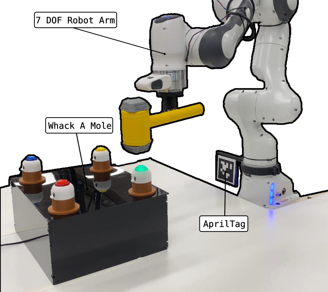
Figure 1: The Setup of the robotic arm and the Whack-a-Mole board.
- Franka Robotics’s Emika Panda - The 7 degree of freedom robotic arm.
- An AprilTag - Attached to the robot’s base for accurate localization within the environment.
- Realsense D435i Camera: An RGB-Depth camera ,Used for identifying the moles and getting the sptial coordiantes.
- Servo Motor-Controlled Hammer - Executes the hitting action in the Whack-a-Mole game using an Arduino Nano.
- Whack-a-Mole Game Board - A custom-built , robust game board. The game loop is handled by an Arduino Uno.
Block Diagram
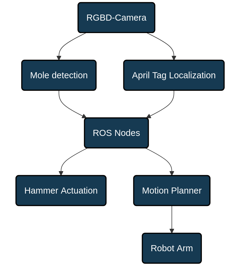
Figure 2: The block diagram.
Computer Vision
Using the RGB-Depth (RGB-D) camera, two tasks were accomplished. First, the localization of the robotic arm relative to the camera was achieved. The camera was mounted above the setup shown above, and localization was performed using an AprilTag using the apriltag_ros package. This ensured that the position of the robot’s base was known to the camera.
Next, the moles needed to be localized as well. Each mole has a distinct color, which can be used for identification. The image stream from the camera has relied OpenCV’s inRange function, which filters out unwanted colors and identifies the centroid location of the target color in pixels (for example, the coordinates 200,600 could correspond to a high concentration of the color red). By using the RGB-D camera’s intrinsic information, the actual location of these colors in the real world could be inferred relative to the camera. This information can then be combined with the robot’s location to determine the moles’ positions relative to the robot. These locations are published to ROS’s tf-tree , which was a way to interface this information with the ROS nodes.
Motion Planning
Once the target was identified , the MoveIt was used to plan the motion of the robot. The motion planning consists of three primary components: motion planning, planning scene, and the robot state.
- Motion Planning - Allows for planning paths from any valid starting joint configuration or pose to a goal, supporting both Cartesian path planning and planning to a named configuration. It also allows plans to be executed immediately or saved for later use.
- Planning Scene - Enables dynamic manipulation of the scene, including adding/removing objects and attaching/detaching collision objects to the robot’s end-effector, as well as loading a planning scene from predefined parameters.
- The Robot State - Performs inverse and forward kinematics (IK and FK) for various poses and joint states, and retrieves the most up-to-date joint configuration or end-effector pose.
ROS Nodes
The the was split task into different components for modularity, allowing each part to be developed and maintained independently, implemented as ROS nodes.
- Camera Node - Responsible for identifying the moles.
- Game/Comm Node - Locates the AprilTag, and puts everything togather using the information from the Camera Node. It also triggers the MoveIt API to generate a motion plan towards the target mole. It also swings the hammer.
WHAM!
Now that everything is set up, the hammer is actuated. The process is then repeated for whichever mole was lit up.
Figure 3: The system in action visualized in RViz.
Acknowledgments
This was a group project, and a lot of fun! I had the pleasure to work with these guys:
David Khachatryan, Haodong Wang, Sairam Umakanth and Pushkar Dave.