The arm assistive exoskeleton is worn on the arm and forearm, providing assistive force to help with lifting, reaching, grasping, holding, and carrying. It is designed for individuals with muscle weakness from peripheral neurological conditions, such as traumatic or neuropathic injuries, which cause upper limb dysfunction..
`
Introduction
Commended by the Faculty of Engineering Evaluation Committee for outstanding performance at the 2020 Mechanical Engineering Graduation Project Exhibition.
People with muscle weakness from peripheral neurological conditions often experience temporary functional decline. Such people could include, for example, stroke survivors,people with traumatic injuries and more. Basic tasks such as grocery shopping, opening bottles, and lifting objects may become difficult or even impossible, leading to a decrease in their quality of life. The Arm Assistive Exoskeleton was created to assist these individuals in performing such tasks, aiding their recovery (by motivating them to move their arm) and improving their quality of life, making everyday activities more manageable.
The objective was of this project was to design a system that allows the user to regain basic functionality back in their less functional hand . The requirements were defined to be grasping and lifting of an item with a diameter/width ranging from 0 to 100 mm and a maximum lifting weight of 1 kg. All while weighing around 1.3 kg, in order not to encumber the user too much.
A prototype was manufactured as a proof of concept.
Overview
The CAD design was done using SolidWorks, here is an overview:
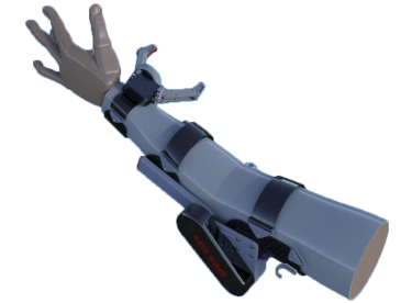
Overview of exoskeleton arm
1. The Arm Attachment
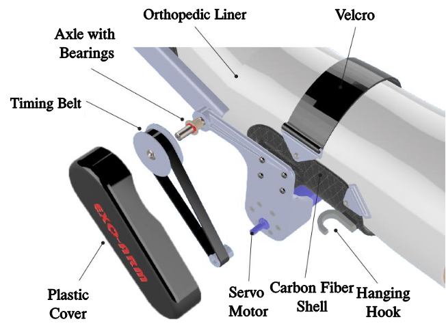
A detailed look on the arm attachment and the flex mechanism
his is the part worn by the user. The frame components, designed to rest on the arm, feature a foam core for comfort and a carbon fiber outer shell for strength. A DC motor is mounted on the upper arm and connected to the forearm by a timing belt. When the motor spins, it drives the movement of the arm, assisting the user in flexing their arm.
2. The Gripper
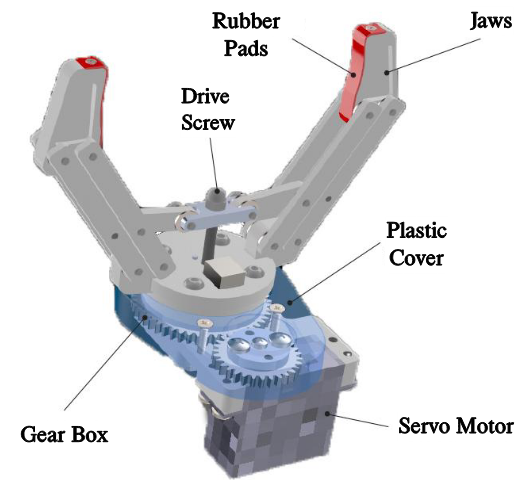
A detailed look on the arm attachment and the gripping mechanism
Since the user has lost some strength in their arm, simply flexing it isn’t enough—gripping objects is also essential. To address this, the gripper was designed. It is a parallel gripper, meaning its jaws remain parallel to each other as they open and close. The gripper is controlled by a special glove worn by the user, allowing them to control the gripper to grasp objects.
The Design Process
The mechanical parts were design in SolidWorks, and for the prototype, manufactured in a variety of methods such as CNC milling, laser cutting, and 3D printing. The control was done with an Arduino Uno.
Structural Analysis
In order to know what kind of motor to use, a structural analysis was done. The assumption is that the system is slow enough that it is most of the time in equilibrium.
1. The Arm Attachment
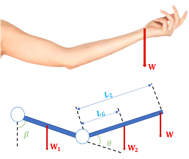
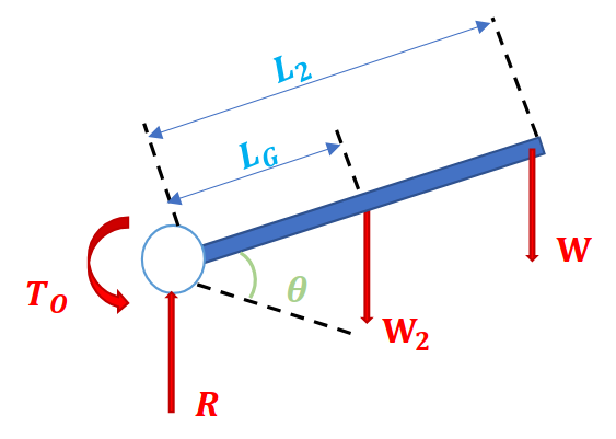
Free body diagram of the arm attachment.
First, let’s observe the figure above, which illustrates the general situation: at certain tilt angles (denoted as 𝛽 and 𝜃), while the gravitational force of the raised object acts downward. The complete situation is depicted: additional forces act on the hand besides the weight of the raised object. These additional forces are the weights \(W_1\) and \(W_2\), associated with both the hand’s own weight and the weight of the system attached to the hand.
\(L_G\) is the distance to the center of mass, which is a weighted average of the hand’s weight and the system’s weight. \(𝐿_2\) represents the length of the forearm.
Isolating the forearm portion
Using anthropometric tables , using average heights and weights of men and women, we were able to get actual numbers for these lengths. It was then inferred that the required motor needs to have 3.5 Watts of mechanical power output, which was useful when choosing the motor.
The Gripping Unit
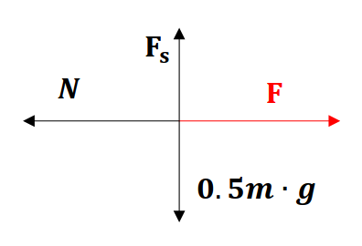
Free body diagram for the gripper
In order to find the force required to grip a mass using gripping pincers, let’s assume a static and symmetrical situation, as can be seen in the free body diagram of the system in the figure above. The coefficient of friction, which affects the force required for gripping, must be taken into account.
\(F\) – the force required for gripping, \(F_s\) – the static force required to prevent slipping, \(N\) – the normal force, and \(m\) and \(g\) are the mass and gravitational acceleration, respectively.
Thus, the gripping force \(F\) was amounted to be:
\[F = \frac{m g}{2 f_s}\]
Where \(f_s\) is the coefficient of friction of the gripper with the mass. It depends on the material and texture of the gripped surface , so an arbitrary value of 0.4 was taken into consideration while. Using this value, it was possible to infer what force is needed from the leading screw that is connected to the servo in the base of the gripper. Using that information and the pitch of the screw it was possible to infer what type of motor would be needed for the desired gripping, assuming \(m = 1 kg\).
Power and Control
For the demonstration of the system’s use, an initial and conceptual design was made so that the system will work. This section is meant to provide an idea of the electrical and control design in the system but does not serve as a reference for the design of the finished product.
Main consumers (maximum consumption):
Grip motors – 12W
Elbow motor – 15W
Controllers – 1.2W
For this condition, a power drill battery – 18V, 3Ah wis to be used. This allows for a theoretical continuous working time of 114 minutes. The battery’s mass is 680 grams.
By using voltage converters, the current will be supplied to all electrical components. The maximum current for the design of the electrical cable is 1.2A.
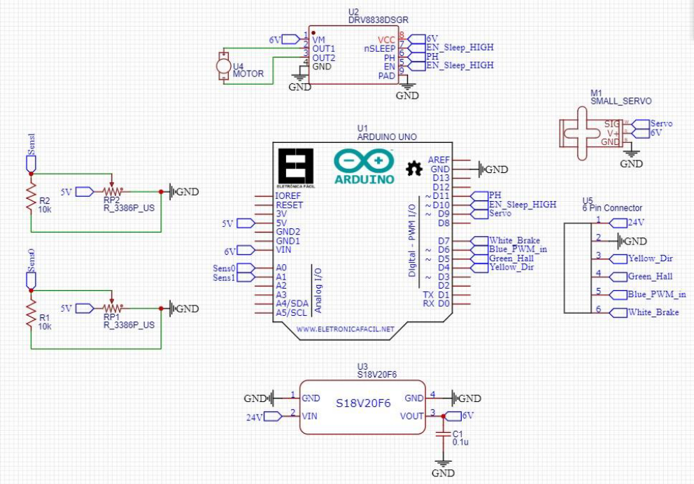
Electrical schematic for the prototype
The system control is to be using a microcontroller of the Arduino Uno type.
The spatial orientation sensor (gyroscope) is to be of the MPU6050 type with 6 degrees of freedom.
The Prototype (!)
Within the given time frame, we successfully built a prototype as a proof of concept.
The prototype in action
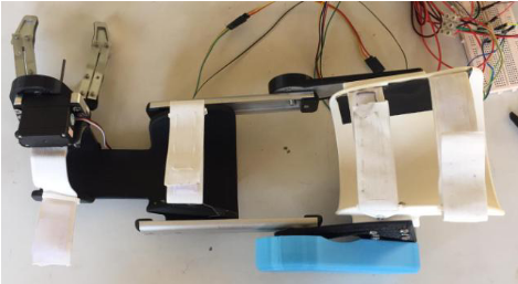
The prototype
Acknowledgments
This was a group project. Without these guys, all of it would have fallen apart.
Yogev Naim , Noam Amitai